
Why is it a good idea to create an account
It is really worth creating an account because you can save your work for later, order something you've designed in the past, and process your orders more quickly.
Are there any safety issues associated with the power supply?
There are three stand-out safety issues with the means of power provision. Electric shock, fire, and explosion. The electric shock really only applies with EM products supplied by mains. Fire can be a problem if circuits aren't fused. All the modules designed are protected, but it is necessary to ensure that any external power supply is protected by a fuse or equivalent. Lithium batteries that become over loaded can explode.
Only deal with open mains if qualified; all the EM's circuits are designed such that lithium batteries are controlled and don't go into a dangerous mode. Make sure all external devices are properly fused.
Using Auto-size on a design
When you have finished picking your design's Modules (Interface, Controller and Power), Use the green Auto-size link and it will reduce your PCB to the minimum size possible with the Modules you've chosen.
You can use Auto-size at any time. It will also correct a PCB, which will be marked red, when the Modules you've chosen will not fit on the PCB size specified.
What is the Commercial Specification?
The Commercial Specification covers all matters financial relating to your design. It shows how much the design will cost to manufacture in volume, and it gives a 'discounted cash flow' estimation of how much you need to earn with your design to make it viable (obviously this comes with a number of assumptions).
Should I design the PCB shape and size or select Modules first?
Whether or not to start with Modules or PCB design depends on the status of your development. If you have a known enclosed space into which you need to fit your PCBA, then use the right hand side of the Design Area to dimension the PCB first.
If you want to experiment with sizes and shapes use the left hand side of the Design Area and pick your Interfaces, Controller and Power Modules first.
What is Resource Usage?
Resource Usage is a measure that allows you to assess how much of a Controller's resources have been used by whatever design you have implemented.
It is of course possible to pick any Controller Module that has sufficient resources to implement your project, but what stops you picking a 120 pin, expensive, Controller for something that is only lighting a couple of LEDs. It would add cost and size to something that didn't need it.
The answer is to pick a Resource Usage figure that is as high as possible.
Why can't I have two Controllers?
Technically, you can. There is no reason why a design can't be configured to have master and slave Controller Modules. The reason it is barred by the EM is it is complex for those who don't really understand what is being implemented, and the EM is about making this process easy. Another reason the EM doesn't implement multiple Controllers is greater than 99% of product designs just don't require it. If you really do want multiple Controllers as a special don't hesitate to
contact the EM via email, and it will set them up for you.
How do I make a choice of Power Module?
There is a little to understand when it comes to selecting a Power Module, but nothing that will be a problem. The main topics, that have been split into other FAQ questions, are:
1. Shoud the device to be powered by a power supply or a battery?
2. What is the space available for the power supply?
3. Should a rechargealbe or non-rechargeable battery be used?
4. How long will a battery last?
5. Can the battery supply pulsed current?
6. Are there any safety issues associated with the battery?
7. Are there any safety issues associated with power suppy?
8. Is it possible to specify a power supply and include battery back up with it?
Find the FAQ question for whichever of the above topics is important to you and the answer will be provided.
What is a Raspberry Pi? Why should I use it?
The Raspberry Pi is a very small and cheap PC (personal computer). It has its own operating system and can be used to control and use equipment that is very demanding (video streaming, cameras, etc.). Effectively, it makes possible to put a computer into the electronic design on a PCBA.
This gives all the power you'd normally expect from a computer on a small PCBA - running Excel spreadsheets or whatever.
Don't use a RPi when an Arduino would do, but hopefully this explains how powerful the Raspberry Pi is.
Raspberry Pi is a little 'hobbyist'. If your application is professional, e.g., a medical device, don't hesitate to get in touch with the
EM and request some specialist support - there are other manufacturers of similar products that are better supported and more applicable for demanding applications.
What is an Arduino? Why should I use one?
Arduino is a company that makes very useful prototyping boards. These take the world of embedded microcontrollers up to a level that allows people who aren't fully fledged electronics engineers to develop products with complex electronics and software control in them. The hardware comes in modular PCBs and Arduino have developed a very user friendly interface for writing software for the hardware (all the complexity is dealt with for you - it is really quite easy).
The problem is that, even though you make a fully functioning prototype, it is a bag of wires and PCBAs that it aren't possible to manufactuer or sell.
The is where the Electronics Machine comes in. You can take the Arduino core (just the bit that controls), add whatever Modules you want (Interfaces like temperature sensors or whatever), and produce a neat, one off, small PCBA with only what you want on it. There is nothing stopping this configuration going all the way to market.
How do I move to the 'Next' stage?
The main stages that must be passed through to get to an EM design that can be manufactured are the specification of Interfaces, a Controller, and a Power Supply. After this it is necessary to click the 'Next' button on the top right hand corner of the Design page.
So, if you are starting with Module choices rather than PCB size specification, pick your Interfaces, pick your Controller, and finally pick your Power Module. Then click 'Next' in the top right hand corner of the Design page and it will take you to the Specification page. When ready to order just use the green Checkout icon.
How can I contact customer support?
At the top right hand corner of every Electronics Machine webpage there is an email and telephone number. To speak to someone please call between 9am and 5pm (UK time), and/or email at any time using the address shown.
Why is there so much difference between the cost of one manufactured PCB and ten?
There are significant costs involved in setting up to make just one PCBA, but as the number of PCBAs ordered increases these are quickly amortised. Despite this, never make first prototypes of PCBAs in numbers above 5 if it can be avoided. The nature of development is such that mistakes will be made and things learnt in early prototype iterations - things change. If a large number of PCBAs are made on an initial spin it is quite likely that the result will be lots of faulty product, rather than just a few.
What if I want to manufacture my PCBA elsewhere?
This is no problem at all. When on the Specifications page check the 'I wish to manufacture my PCBA with the Electronics Machine'. When the design is complete you will receive a full set of manufacturing and design data files. These will enable you to manufacure your design wherever you like and/or make modificaitons to your design as you see fit. Please note that warranty for products not manufactured by the Electronics Machine is void.
What if I want my PCBA manufactured?
This is easy. On the specifications page, just tick the checkbox labelled 'I wish to manufacture my PCBA with the Electronics Machine', and enter the number of prototypes you require (less than ten for prototyping - contact
[email protected] if more required).
What is the Technical Specification for?
The Technical Specification contains all the necessary design and performance detail to use, modify, manufacture or technically assess the system that has been designed. It references Modules, which have there manufacturing and design files supplied to customers separately. Any particular characteristics of both the system and individual Modules are listed. For informaiton, the electronics are designed using Altium, project files for which are available at the request of the client.
What is the Commercial Specification for?
The Commercial Specification provides a range of fundamental commercial data related to the system designed with any relevant assumptions listed. The data supplied: £ProductionCost vs. BatchSize; break-even analysis for both B2C (business to customer) and B2B (business to business); and an £ROI (return on investment) assessment.
What does 'Connectors IGS file' or 'Connectors .dxf' mean?
.dxf and igs flles are flies that can be uploaded that give information about the physical dimensions of something. These files can be developed by the EM's customers to specify the exact shape, including cut outs, of a PCB. The files also allow for bespoke information to be added, e.g. the exact position of a key component - say a connector.
What does 'standard' connectors mean?
Standard Connectors means that the client will accept default connector types positioned as the EM deems most appropriate. Connectors for the interface modules are as defined in the Modules themselves. Likewise the Power Modules. If you wish to have bespoke positioning or specifiy your own connectors, upload a .dxf file with your requirements and they will be followed.
What are mounting holes and how do I implement them?
Some PCBs are fixed into mechanical assemblies/boxes/enclosure by their edges, but other need to be fixed securely in place using screws. In order to do this it is necessary to put holes in the board. That is what Mounting Holes are. In the design area, the number and diameter can be selected and it is possible to specify that the bore of the hole is plated for grounding. Grounding is normally used for safety reasons if the board has relatively high voltages on it, e.g. 240V mains. It is possible to put some impractical sizes in at this stage. The mounting hole diameter should never have a diameter more that a tenth the length of the side of the PCB it is on.
What does 'screw terminal with flying lead snapout' or FLHSnap mean?
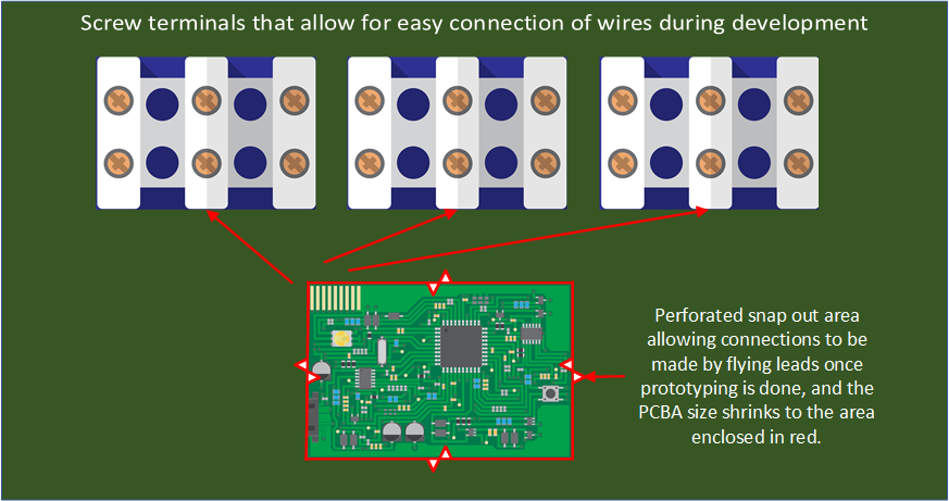
A flying lead is single wire connection to a solder pad on a board, using solder. This type of lead to a PCB will result in the least amount of space being used, but it doesn't lend itself to easy testing because each wire connection must be individually soldered. The most convenient type of connector for prototyping is the screw terminal, which will allow bared wires to be connected easily.
The FLH Snap confiiguration takes all IO (input and output digital lines) from whatever controller is used out to screw terminals on the PCB - very convenient for development, but bulky. When the design configuration is complete, the centre of the PCB may be 'snapped' out leaving the same connections as were used for screw terminals availalble as flying leads. The illustration explains this.
FLHSnap allows screw terminal connection during development and flying lead once developed (or headers).
What are Power Modules?
Power Modules allow for power to either be an integral part of the board (battery), or for power to be made available to teh PCB, e.g., 240V mains or a 24V dc supply. Note that the EM only facilitates power for itself. External devices that require significant current must be externally supplied but can still be controlled by the EM using a switched ground.
What are Modules?
Modules are functional units that you may want to include in your design. There are 3 types: Interface, Controller and Power. It is usual for there to be one Power and Controller Module. There can be as many interface modules as are desired.
What is the Design Area?
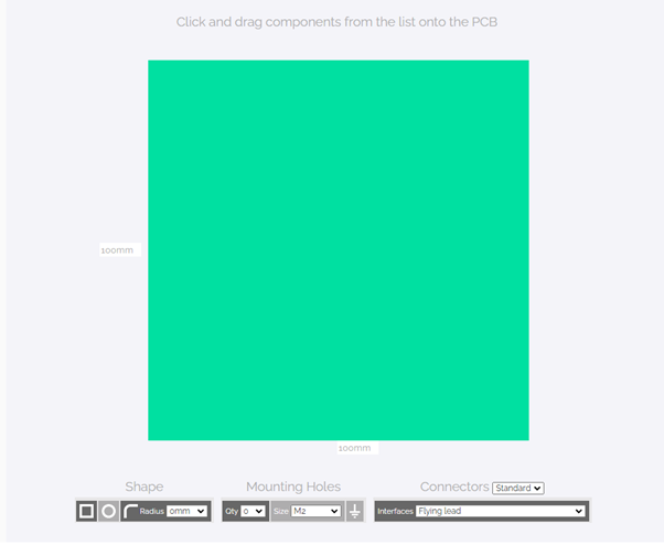
The design are is where Modules are loaded and the PCB system is designed. Its components are described separately.
What shape PCBs can I have?
The standard shapes, which are most cost efficient, are a square, rectangle, rectangle or square with radii, or circle. It is possible to have any shape required by uploading a .dxf or step file, but note that this adds a little cost.
What are Controller Module Brands?
Brands are major different types of families/companies that are available on the market. Three examples would be Arduino and it all its controllers, PIC Microcontrollers, and Arm microcontrollers.
What is a Controller Module?
Once Interface Modules have been chosen, it is usually necessary to measure and control to make the system do what is required. This is done by a Controller Module. An example might be a laser being used to measure distance (read into the controller), and the need to perhaps drive a motor to a position depending on the distance measured. The best way to think of the Controller is as the 'brain' of the system. What it actually does is controlled by firmware (software for electronic chips on a PCB).
What are Interface Modules?
Interfaces are the functions needed to connect to the outside/human world. These Modules can be such that something is measured from the outside world, or they can be such that something in the outside world is driven. These are the Modules that really define what is being designed. Some examples are: BLE Bluetooth Module, pressure sensor, temperature sensor, motor driver, switch, LED, screen, etc. To decide what's needed think about what you want to measure and process, and what you want to drive.
How do I select Modules and place them on my PCB?
Do your interfaces first, then controllers, and finally the power source. The easiest method is to simply click the Module required and it will be automatically dropped into the design area. Modules can be dragged across, but this is more time consuming.
Can I have a battery and a power supply?
The short answer is: yes. It is common in some designs to configure a product such that it has power from the mains but also battery back up. If a Module that suits your requirement doesn't seem to be available, pick the Power Joker Module and the EM will include a Power Module with battery back up to the specification you require.
What is the Technical Specification?
The Technical Specification (TS) defines all the technical characteristics of your design. From it the EM can design your product, and you can check that it is what you want.
Should a rechargable or non-rechargeable battery be used?
The short answer is it depends on how long a non-rechargeable one will last. If a non-rechargeable one can last either the life of the product, or last for sufficient time to make it not unreasonable that it is taken out of the device and replaced, then a non-rechargeable battery is probably the best solution. If not, but a battery and not a power supply is the best way of getttng power to the device, then it is probalby best to use rechargeable one. If you wish to find out roughly how long a battery will last follow this link to
JonJu's battery life simulator.Can the battery chosen supply pulsed currents?
There are two key electrical requirements for a battery: does it have sufficient maximum charge capability, and can it supply the maximum current that's required. The first is determined by the mAhr rating of the battery and whatever the use conditions are -
see JonJu battery life estimator. The maximum pulsed current should also be quoted in the technical datasheet or Module data (often datasheet doesn't have this). Bear in mind that even if a given level of high pulsed current is within the capability of a battery, it will reduce the life of the battery and reduce the estimated mAhr rating.
What is the space available for a power supply (Space Usage)?
This is rather an obvious point, but there are things to think about. Obviously, the space available is whatever is available in the enclosure that is intended for the electronics, but bear in mind that batteries need wires and (if not PCB mounted) holders. Also, lithium batteries don't like being constrained - leave a small gap around them in the enclosure design.
Note that for each power Module a Space Usage (displayed on the front of the icon) is quoted. This is the space the power module is expected to take up on the PCB divided by the space all the other components take up. Be careful about vertically mounted PCB batteries. These may take up limited space on the PCB but have a big effect on the volume requirements for any enclosure.
Are there any safety issues associated with the battery?
This answer assumes that battery voltages are low - no electrical safety risk.
Lithium batteries can explode when they either become hot or have a short circuit applied to them. This is obviously not a good thing. This is overcome with electronics that monitor the core characteristics of the battery and manage its load current so that a short will not occur.
Should my product be powered by a battery or a power supply?
This question really is one that is settled by the market the product is intended for, and what's possible, but there are certainly some guidelines the EM can assist with. It is all a question of how energy efficiently a given product can be made to be.
Not having, ever, to plug a product in to a mains supply is a big advantage. This is only possible if the battery, which will probably be of a non-rechargeable type, has sufficient energy to power the product for its expected life. A watch or calculator are examples that might fit this model. Of course, this is often not possible. The two knock ons from this are the space available and the liftetime of the battery. A battery lifetime calculator can be found at
JonJu Tech Ltd.,
The other key factor that rears its head when selectiing a battery that is likely to power the device for its entier life is size versus the space available. The kinds of product for which a lifelong non-rechargeable battery are suitable are typically small - so a large battery is inappropriate. There are two factors to take into account when assessing the suitability of a battery or Power Module: the physical size of the battery in question and the size of its connection system. Details for this are available from the Module data, and the datasheet for the key component in the Module in question. Furthermore, there is a Space Usage metric calculated for every Power Module. This is the space taken by the battery's real estate usage on the PCB divided by the total area taken up by all the other components on the PCBA.
Make sure that account is being taken of both the battery volume and its connector. Also make sure that the volume and orientation of the battery is being considered - a vertically mounted battery may have a low Space Usage but be of very significant volume.
The next level is a rechargeable battery that can be re- charged, usually by portable devices. Battery life and volume are the same as in the case above. To make estimates of life for such battery systems use
the JonJu battery estimator link. Size limitations must be assessed in much the same way as for a non-rechargable battery, but don't forget that there is an extra limitation with a re-chargeable battery. There is a limit to the number of times it can be charged and discharged before failure. Also, the life is dependent on the current drawn when loaded. All this can be assessed via the battery datasheet, a link for which may be found with 'More' shown on the front of each Module.
Usually, the drive is to get size down, and Lithium is the best battery chemistry to achieve this. For a better understanding of battery chemistry and all the factors affecting battery selection, see the
JonJu Tech Ltd.'s document on battery technolgy and chemisty.
The next level of power supply is an external power supply that is driven by mains electricity. These will normally plug into a socket and connect to the PCBA via a jack plug or something like it. The voltage at the jack plug is typically low - say 9 or 12V.
Finally, the power supply may be implemented via a power supply mounted on the EM systems itself, in other words the connection is directly from mains electricity to the PCBA. The EM does provide Modules like this.
Mains voltage is dangerous and will be open on the EM's PCBA if a design using the last scenario has been used. If you don't know the implicaitons for safety from the use of such a power supply please contact the EM for assistance.
How do I know which pins have been used for my interface?
When coding in Arduino IDE you'll need to know where your interfaces have been connected, please have a look at design files which get after placing order. Please use the pin map below for your coding.
For Arduino Nano, the pin map is following:
D0 = PD0,
D1 = PD1,
D2 = PD2,
D3 = PD3,
D4 = PD4,
D5 = PD5,
D6 = PD6,
D7 = PD7,
D8 = PB0,
D9 = PB1,
D10 = PB2,
D11 = PB3,
D12 = PB4,
D13 = PB5,
A0 = PC0,
A1 = PC1,
A2 = PC2,
A3 = PC3,
A4 = PC4,
A5 = PC5
What is a switched ground?
It is often necessary for a system designed by the EM to control an interface that has much greater power requirements than the EM has. The switched ground is used to overcome this. The exteranal device is connected to the positive of an external supply, but its negative connection is made through the EM system (switched ground Interface Module are usually FETs). This means the EM system only has to sink the current, not supply it.
Why are there so few screens in the EM?
Use of wireless technology (Bluetooth, Wi-Fi) is encouraged. The reason is the power of smart phones and tablets makes for better products, smaller footprint and lower cost. If a particular screen is essential then use the Joker in the Interfaces and the EM will implement it in your design.
Are EM designs EMC approved?
EMC design precautions and protocols are rigorously followed, but there can be no guarantee of EMC compliance without a formal verification and validation with an accredited test house.
Find out more about EMCDo I have to manufacture my EM Design with the EM
No is the short answer. It is absolutely valid to order a design and have all the design files and manufacturing files sent to you. You are then free to have the design manufactured wherever you like. This can transpire to be cheaper, but note that the EM can't take responsibility for manufacture of products outside its control.
Why is the number of prototypes I can manufacture restricted to 10?
It is never a good idea to order a lot of prototypes the first time you are ordering something. Remember, even though the EM's Modules have been tested, there can be no guarantee that what you've designed will do exactly what you expect. To give you an example, imagine that you have designed a microcontroller based pressure sensor that you intend to sell to Tesco. The Module you've designed works fine so you take it down to Tesco to try it. Perhaps what they didn't tell you was the intent to use it in a refrigerated room, and the pressure is inaccurate at temperature below 5 degrees celcius.
This is why it is alway good to order early prototypes in low quantities - at least until you are sure it is fit for purporse.
If you have reasons for believing it in your interest to order more, please
contact the EM and we'll help you.
Why does the manufacture cost per item reduce so quickly with volume?
It costs a lot for a manufacturer and assembler of PCBAs to set up its machines to produce a particular design, but this cost is then spread over the number ordered. So if the set up costs are £100, and the PCBA costs £10/item to produce, ordering 1 will cost £110. If 10 are ordered, the cost will be £100 + £100 = £200. Therefore they only cost £20 each if 10 are ordered. These are very arbitary figures but should help to clarify things.
How reliable is component supply for EM PCBAs (manufacture)?
Electronic component delivery is, at the time of writing (30/1/2022), rather variable. This effects the delivery of EM boards because the prototypes can't be manufactured until all the components are available. Nevertheless, the EM mitigates this by: using only parts that have been verified via Silcone Expert or some other verificaiton package; keeping open and strong links with all the distributors and suppliers; and providing alternative designs that fully meet module specificaitons. If there are any problems or questions please click the email link at the top right hand corner of this page and the EM will answer any question you may have.
What is the difference between double sided and single sided PCBAs?
This is simple. Single sided means that there are the PCBA only has components on one side of the board. This of course dictates that double sided means there are components on both sides of the board.
What are PCB layers?
Layers are the number of copper layers a board has. When PCBs are made they are laminated layers of copper and FRR (the insulating material) set up like a sandwich. A board will have an even number of layers - suits manufacture.
What does immersion mean?
This is a final plating process during the PCB manufacturing process (before any components have been soldered), usually in silver or gold. Its purpose is to protect copper pads intended for soldering from oxidation that could reduce the quality of the electrical joins made using solder.
What does ounces of copper (oz Cu) mean?
This determines how much copper will be available on a given layer - the greater the quantitiy of copper the more current the circuit can carry. The measure harks back to the imperial measurements of yesteryear, and it means the number of ounces in weight of copper per square foot of PCB. So, 1 oz Cu means that if a square foot were covered on this measure it weigh 1 ounce. The most usual weight is 1ozCu, Higher weights are predominantly for circuits carrying currents of amps.
What is a footprint?
When an electronic component, such as a chip, is placed and soldered onto a PCB it must have a pattern of plated copper areas to allow its to electrically connect through solder joins. This pattern is known as a footprint. Each component has a footprint and these must all be present for it to be possible to assemble the board with its components.
Is it easy to get EM designs manufactured outside the EM?
The simple answer is yes. There are a multitude of PCBA manufacturers all over the globe, and many have good customer support. Such companies will usually help you when there are technical questions to be answered. NOTE: The EM does not take responsibility for any product manufactured outside its auspice - warranty is automatically void in this circumstance.


 The Terms and Conditions of business are available on the Specificaiton page of the EM website. This page is always entered in the design process. The Terms and Conditions must be approved before any order is placed.
 +44 (0)1865 507778
 Wantage, Oxfordshire
 How to use the EM tool